we are updating the free tutorial on regular basis . Please keep in touch in future to watch update
Undernoted courses basic learning have been illustrated to learn the basic of the the all courses tutorials. After Buying the exam voucher , you will get 40hrs courses extra to complete the project base tutorials through office 365 / shere point platform . for that you required to learn oneNote . |
|
|
You have selected free tutorial of the AutoDesk for the Autodesk Certified User (ACU) :
Autodesk AutoCAD Certified User Exam
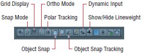
Topics : Creating Drawings: Draw Tools and Settings : Drafting Settings : Describe the Snap and Grid, Polar Tracking, and Object Snap settings.
Autodesk Help:-
Grid & Snap:-
The basic drawing surface which is Grid and makes the canvas in AutoCAD look like graph paper. we can adjust the grid’s measured size and the spacing of its major lines to simulate many types of graph paper. Snap constrains, which enable your ability to draw objects so that the canvas can automatically start and end precisely at grid intersections. Grid and Snap are most helpful when used together so that you can draw objects that snap to the grid.
Let us work with grid and Snap
- Click the New button on the Quick Access toolbar.
- Choose the acad.dwt Imperial template (or acadiso.dwt metric template) from the Select Template dialog box and click Open.
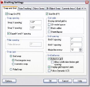
- Right-click the Grid Display toggle on the status bar, and choose Settings from the context menu. Change Grid X spacing to 1g (or 10 mm), and press Tab; Grid Y spacing updates with the same value. Set Major Line Every to 12 for Imperial (or 10 for metric) so that you’ll see darker grid lines every foot. Notice that Snap spacing is set to 1/2g (or 10 mm) by default. Select Snap On, and verify that the Grid Snap radio button is selected in the Snap Type area . Click OK.
- Click the Line tool in the Draw panel on the ribbon’s Home tab. Click the first point near the lower-left corner of the canvas at the intersection of major grid lines (darker lines). Click the second point 2f (or 609 mm) above the first point by clicking the second intersection (or sixth intersection in metric) of major grid lines. Right-click to end the LINE command. It’s very difficult to see the line because the grid obscures it.
- Click the Show/Hide Lineweight icon in the status bar so that the button is highlighted in blue. It’s difficult to see the line because the default lineweight display is too thin.
- Right-click the Show/Hide Lineweight icon, and choose Settings from the context menu. Open the Default drop-down list, select 0.016g (or 0.40 mm, and click OK. The line you drew in step 4 is displayed thicker so that it’s more visible against the grid.

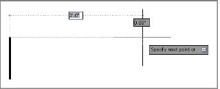
- Type L, and press Enter twice to continue drawing from the last point clicked. Toggle Grid Display off and Dynamic Input on in the status bar. Move the cursor horizontally to the right from the point at which the rubberband is anchored. Notice that 1/2g (or 10 mm) increments are all that show up on screen; this is due to Snap. Snap can be used independently of the grid; the grid is merely a visual drawing aid. Click on the drawing canvas when the dynamic input value reads 2f-0g (or 600 mm), as shown in Figure below. Leave the file open for work in the next section.
|
Your Salary Above $ 66000... Click ...
Ohh! You want More.... be game developer of your choice $ 102000 ....
|
This is Free Tutorial for the user Who will puchase Exam vouture of Microsoft, Adobe, Autodesk
User Name: Date: Count Numer of Free Visit:
|
data-share="true"
data-width="450"
data-show-faces="true">