Learn Game Development in Unity Server
Learn Game Development in Adobe Flash with help of Photoshop and After Effect
Learn Game Development with javascrit
Learn Game Development with C++ and DirectX 11 é DirectX 12, 2D, 3D
Learn Game Development with Robotics Aplication
Learn Game Development with WebGL 2D, 3D
Aeduino for Engineering Project.
The Process of Arduino Engineering
now we will discuss the engineering process and how you can use it streamline your prototypes by avoiding problems with hardware and software and keeping to a fixed schedule. Throughout this book, you will have projects that will be organized into a sequence I like to call the ?engineering process.? Here?s a quick summary of the sequence:
- Requirements Gathering
- Creating the requirements document
- Gathering hardware
- Configuring the hardware
- Writing the software
- Debugging the Arduino software
- Troubleshooting the hardware
- Finished prototype
As you can imagine, even this summary of engineering process is
very effective when prototyping, which is why we will use it with the Arduino in
this book. What is the Arduino? The Arduino is a very customizable
microcontroller used by hobbyists and engineers alike. Also, it is open source,
which means that the source code is available to you for your programming needs;
the integrated development environment (IDE) (where you will be writing your
software) is free, and most the resources you can find are open source. The only
thing you have to buy is the Arduino microcontroller itself. The Arduino is
supported very well on the Web and in books, which makes it very easy to
research how-to topics; a few sites that will help you get started are
http://www.arduino.cc/
and
http://tronixstuff.wordpress.com/tutorials/
.
But this book is more than simply a how-to reference; this book is going to
teach you the engineering process?a skill that is useful for making projects
more readable, efficient, and reliable.
Gathering Your Hardware
Before we examine the engineering process steps, it?s important to know some of the parts and materials you?ll need. Throughout this book, you will need the following pieces of hardware to complete the various projects we?ll be working on (for a complete list of hardware used in this book, please see Appendix A ):
-
Arduino Duemilanove or UNO: You can use either the Duemilanove or
the UNO micro-controller for this book (see
Figure
1-1
). They have multiple I/O ports for sensors and motors. We will be
using these I/O points to control and keep track of the various projects in
this book.
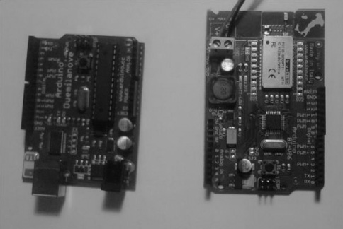
Figure 1-1. Arduino UNO (left) and Duemilanove (right)
-
ArduinoBT or Bluetooth Mate Silver: I suggest using the Bluetooth
Mate Silver modem for this book because it can make your Arduino Duemilanove
or UNO behave like an ArduinoBT at half the cost. Also, the ArduinoBT does not
have a 3.3V output point, so you would need to add circuitry to the Arduino in
order to get 3.3V, which you need in
Chapter
6
of this book.
Figure
1-2
illustrates these two pieces of hardware.
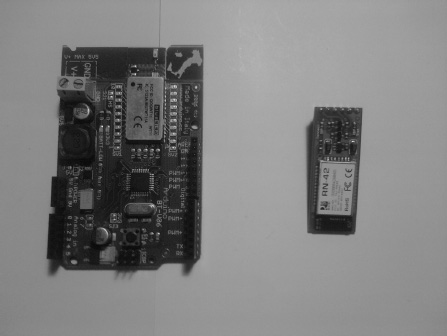
Figure 1-2. ArduinoBT (left) and Bluetooth Mate Silver (right)
-
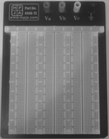
Solderless breadboard: Another very important piece of hardware is
the solderless breadboard (see
Figure
1-3
), which is used to implement your circuitry. For this book, you need
to have a midsize solderless breadboard. It will be used in both the design
and troubleshooting phases of the projects.
- Wire: We will use a large quantity of wire in this book; you can get a wire jumper kit at almost any electronics store.
-
Arduino shields: We will be using several shields in this book,
including the Motor, GPS, GSM, and LCD shields (see
Figure
1-4
).
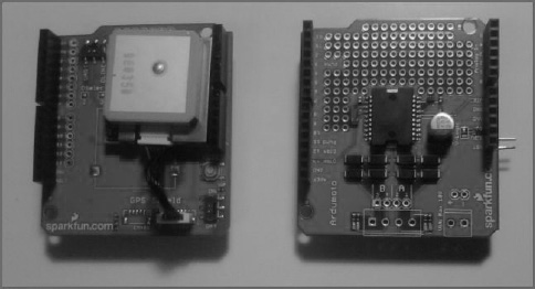
- Motor shield: This shield is used to control motors up to 18V. It includes a surface-mount H-bridge, which allows for a higher voltage motor to be used as well as for control of two motors. For more information on H-bridges, please see Chapter 3 .
- GPS shield: This shield is used to get positioning information from GPS satellites. It uses the National Marine Electronics Association (NMEA) standard, which can be parsed to tell you any number of things such as longitude and latitude, whether the GPS has a fix, what type of fix, a timestamp, and the signal-to-noise ratio. For more information on GPS systems, please see Chapter 5 .
- GSM shield: This shield will allow you to use the power of the Global System for Mobile Communications (GSM) to send text messages back and forth at great distances; this shield also uses a standard protocol called the GSM protocol.
- LCD shield: We will use this to add images and life to our robots. The LCD shield can also be used to create your own user interface for your robot or any other project that you would like to persue.
-
Sensors: These are very important because they give your projects
life. Some sensor examples are PIR (Passive Infrared), sonar, and temperature
(see
Figure
1-5
).
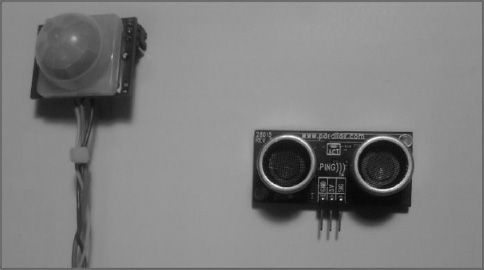
- PIR sensor: This is an outstanding sensor for detecting changes in infrared light and can detect changes in temperature. It is also great at detecting motion, and that?s what we will use it for.
- Sonar sensor: Sonar sensors are good at detecting objects in their surroundings. The Sonar sensor we will be using is a Parallax sensor that uses digital pinging to tell how far away an object is.
- Temperature sensor: These sensors are used to read temperature. To use them, you first scale the voltage to the temperatures you want to record; you can find more information about this sensor in Chapter 6 .
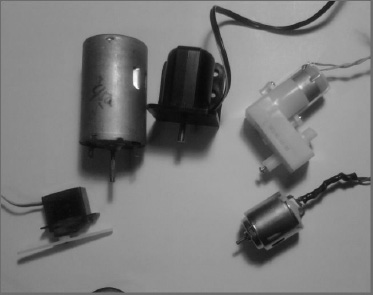
-
Servos and motors: We will be using motors and servos to control
many aspects of the projects (see
Figure
1-6
).
-
Miscellaneous: These are the most common components, such as
resistors, capacitors, LEDs, diodes, and transistors (see
Figure
1-7
).
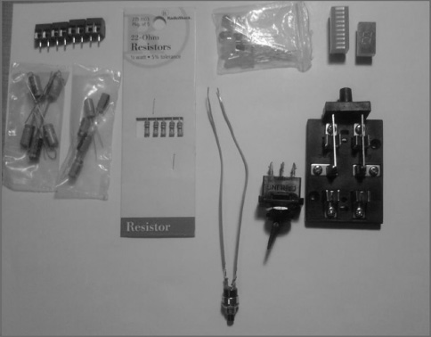
Figure 1-7. Miscellaneous pieces of hardware (terminal blocks, capacitors, resistors, LEDs, and switches)
Gathering Your Tools
You will also use a variety of tools; this section will briefly describe them. For a full list of tools you will need, please see Appendix A.
-
Soldering iron: This tool is used to connect circuits to each
other; we will use it mostly to connect wire to circuits (see
Figure
1-8
).
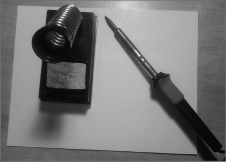
Figure 1-8. A Soldering iron and its stand
- Solder: You will use this in conjunction with the soldering iron; it is the metal that connects the circuits together. Solder has a very low melting point.
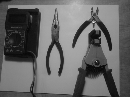
- Needle-nose pliers: These pliers are very important; they are used to hold wire and circuits in place, wrap wire around circuitry, and so on (see Figure 1-9 ).
- Magnifying glass: This tool is used to better see circuitry.
- Dikes: These are used to cut wires (see Figure 1-9 ).
- Wire stripper: This tool is used to take off wire insulation (see Figure 1-9 ).
- Multimeter: Possibly the most important tool you can own, this tool allows you to read voltage (AC (alternate current) and DC (direct current)), amps (ampere), and ohms (see Figure 1-9 ).
- Scientific calculator: This allows you to do various calculations (Ohm?s Law, voltage divider, etc.).
Understanding the Engineering Process
The engineering process is very useful in making your designs more efficient, streamlined, and comprehensible. The process consists of gathering requirements, creating the requirements document, gathering the correct hardware, configuring the hardware, writing the software, debugging the software, troubleshooting the hardware, and the signing off on the finished prototype.
Requirements Gathering
One Day, when you?re an engineer, you may be asked to go to a company and assess its needs for a particular project. This part of the engineering process is crucial; everything will depend on the requirements you gather at this initial meeting. For example, assume you learn that your client needs to blink an LED at a certain speed[insert an example case here to flush out the idea]. And for that task, you and the client determine that the Arduino microprocessor is the best choice. To use the Arduino to blink the LED [insert the example task here], a customer needs an LED to blink at 100ms intervals.
Creating the Requirements Document
Based on the client?s needs and your proposed solution, the following is a very simple requirements document:
-
Hardware
- Arduino
- LED
- 9V battery
- 9V battery connector
- 22ohm resistor
-
Software
- A program that blinks an LED at 100ms intervals
Mind you, this is a very simple example, but we will be using this format for the rest of this book. One of the reasons you create a requirements document is to stop feature creep. This happens when a customer keeps adding features to the software and/or hardware. This is, of course, a problem because you will be working more hours without more pay on a project that may never end. You should create a requirements document, so you and the client know what you are doing and the features you will be creating for your project. After you have created the requirements document, you can create a flowchart that will help you debug the software later in the design process (see Figure 1-10 ).
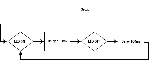
Figure 1-10.Blinking LEDs processes
Gathering the Hardware
The next very important part of the engineering process is making sure you have the right hardware. Your hardware needs should be decided as you?re gathering requirements, but it is important to make sure all your hardware is compatible. If it is not compatible, hardware changes may be necessary, but you should consult the company you are working with to make sure it is satisfied with any hardware changes.
Configuring the Hardware
Once you have the correct hardware, it is time to configure it. Depending on the hardware required for the project, the configuration can change. For example, let?s take a look at the hardware configuration for the blinking LED project.
- Arduino
- LED
- 9V battery
- 9V connector
To set up the hardware, we need to connect the LED to digital pin 13 and ground on the Arduino(see Figure 1-11 ), as illustrated in the schematic shown in Figure 1-12 .
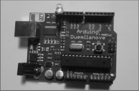
Figure 1-11. The hardware setup for the Blinking LED project
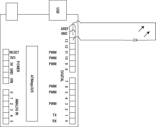
Figure 1-12. A schematic of Blinking LED project
First, we need to install the Arduino IDE. To do this, go to
www.Arduino.cc/en/Main/Software
.
The Arduino IDE will work with Windows Vista or 7, Mac OS X, and Linux systems.
After the Arduino IDE is downloaded to your desktop, it will be in a zipped
format, so unzip the Arduino-0022 file to your desktop. The Arduino
IDE is now installed.
Now that you have the Arduino IDE installed on your computer, you need to make sure it is configured correctly. To do this, open the Arduino IDE, and go to Tools Serial port; select the serial port your Arduino is connected to. Next, select Tools Boards, and select the Arduino board you are using (this book uses the Arduino Duemilanove Atmega328). Once your hardware is configured, it is time to write the software.
Writing the Software
Now, let?s consider the software we need to write. This part of the engineering process is crucial. Let?s take a look at the blinking LED software requirements document to decide what the software will need to do: the LED needs to blink in 100msn intervals. The software might look something like this:
                  // This code blinks an LED at 100ms

const int
                  LEDdelay = 100;  // delay time

void
                  setup()
{
                           pinMode(13, OUTPUT);  //
                      makes pin 13 an output
}

void
                      loop()
{
     digitalWrite(13,
                      HIGH);   // this writes a high bit to pin
                      13
     delay(LEDdelay);          //
                      delay 100ms
     digitalWrite(13,
                      LOW);
     delay(LEDdelay)
                          //
                          this will throw a syntax error due to a missing semicolon


}
 Note When you
try to compile this program to your Arduino, it gives you an error. This is
because of a syntax error that we will debug in the next section.
Note When you
try to compile this program to your Arduino, it gives you an error. This is
because of a syntax error that we will debug in the next section.
Debugging the Arduino Software
The last program failed to compile because of a syntax error . This type of error is because of incorrectly formatted code, such as a missing semicolon (which is why the last program didn?t compile). Here is the revised code:
                  // This code blinks an LED at 100ms

const int
                  LEDdelay = 100;  // delay time

void
                  setup()
{
     pinMode(13, OUTPUT);  //
                  makes pin 13 an output
}

void
                  loop()
{
     digitalWrite(13,
                  HIGH);   // this writes a high bit to pin
                  13
     delay(LEDdelay);          //
                  delay 100ms
     digitalWrite(13,
                  LOW);
     delay(LEDdelay);          //
                  the semicolon is now present and the code will compile

}
Syntax errors are not the worst errors out there. The worst errors you can receive are logical errors; these errors allow the code to compile, but the end result is unexpected. For example, using a greater-than symbol instead of less-than is a logical error, and if it is in a project with thousands of lines, it can be almost impossible to fix.
We can debug logical errors in an Arduino program by using a flowchart to figure out where the values are not lining up.
Troubleshooting the Hardware
The number one tool used to troubleshoot hardware is the multimeter. This tool can save your hardware from being damaged. For instance, if your multimeter detects that your power supply is more than is required, the hardware setup for the blinking LED project could use a 22ohm resistor to keep the LED from burning out.
Finished Prototype
Once you have finished debugging the software and troubleshooting the hardware, you should have a completed prototype that will work under most circumstances. In this chapter, we used a very simple project, but in future chapters, the projects will get more complicated, and the engineering process will become even more necessary to make sure our code is efficient, streamlined, and comprehensible.
Summary
In this chapter, you learned the different pieces of hardware and various tools such as: The Arduino, Arduino Shields, Multimeter, and needle-nose pliers; just to name a few that will be used throughout this book. We then went over the engineering process, which is a sequence you can use to solve problems that provides the format for this book. The steps in the process are requirements gathering, creating the requirements document, gathering the hardware, configuring the hardware, writing the software, debugging the Arduino software, troubleshooting the hardware, and finished prototype. I also defined a few new terms that will help you understand the engineering process, and you learned the differences between logical and syntax errors.